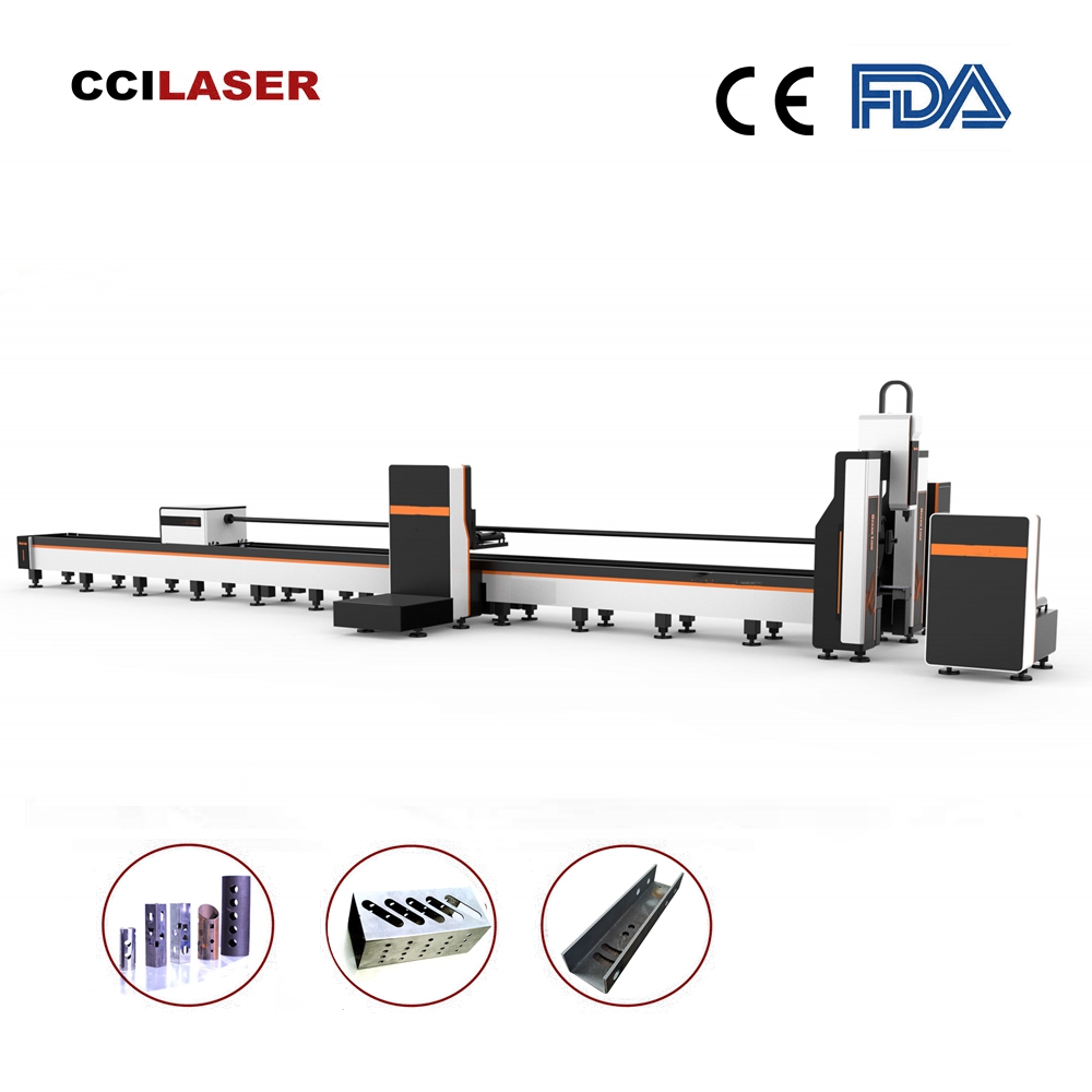
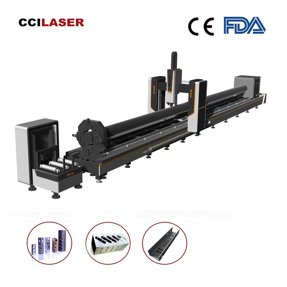
Heavy Duty Metal Tube Fiber Laser Cutting Machine: FLC-12020CT/6020CT
Power supply requirements:
1) 380 V ± 5 % 50 Hz / 220 V ± 5 % 50 Hz;
2) The stability of three-phase voltage is less than ± 5 %;
3) Three wire power supply imbalance less than 2.5 %;
4) It is recommended to use a regulated power supply if it does not meet the above power supply requirements.
Note: The power supply voltage should not have sudden jumps or power outages, otherwise it may cause damage to the equipment, CNC system, and laser.
A good grounding (with a grounding resistance of less than 10 Ohms) is required.
- Machine Configuration
This machine is used for cutting metal round tubes, square tube channel steels, angle steels, and H-shaped steels.
It adopts a 21 inch high-resolution LCD color display, which can display cutting graphics and cutting operation trajectories.
The chuck diameter is 220 mm, suitable for cutting profiles with a diameter of less than 220 mm.
The keyboard adopts a key operation mode, supports USB drive file transfer, and can also manually edit cutting programs.
The biggest advantage of this device is its high cutting accuracy, the ability to install dedicated intelligent trailers, the ability to prevent material sagging, and a 2-year warranty (except for consumables).
Additionally, it supports functions such as pausing, moving forward, moving backward, and adjusting speed during processing.
It can store 4 GB files and can be used freely.
It is driven by high-efficiency servo motors, with fast speed, high efficiency, high accuracy, and smooth operation.
Adopting high flexible shielding wire, it truly resists high-frequency interference and is suitable for various fiber optic models.
The movable crossbeam can achieve the effect of saving tailings.
- Cutting Effects
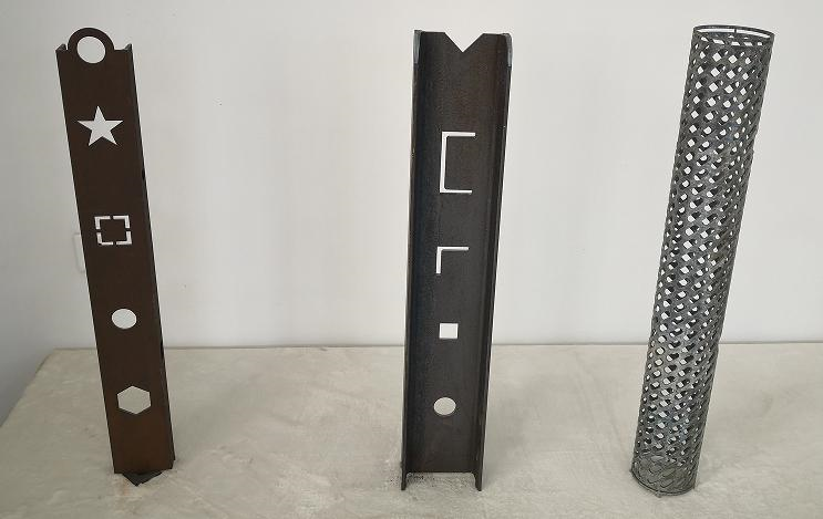
- Equipment usage environment
3.1. Environmental temperature: – 10 ~ + 55 ℃;
3.2. Environmental humidity: Monthly average humidity ≤ 80 %;
3.3. Power supply: Control system power input 220 V ± 10 % 50 Hz, Laser 380 V ± 10 % 50 Hz;
3.4. Gas source: oxygen or nitrogen or compressed air.
- Main Technical Parameters
4.1. Cutting steel pipe specifications
| Cutting material types | Round tube, square tube, channel steel, rectangular tube, H-shaped steel and etc. |
| Wall thickness of fiber optic cutting tube | Maximum 12 mm.
It can achieve cutting 10 mm thickness carbon steel in batch production. |
| Cutting material length | 12000/6000 mm |
| Diameter cross-section | 220 mm × 12000/6000 mm |
| Overall body length | 16000/9000 mm |
| Equipment weight | 3000 kg |
| Cutting accuracy | 0.5 mm |
4.2. Cutting Speed (1500 W)
| Material | Material Thickness (mm) | Speed (m/min) | Air Pressure (MPa) | Air | Cutting Nozzle |
| Stainless Steel | 1 | 24-30 | 1 | N2 | 1.5 mm (Single) |
| 2 | 8.6-12 | 1.4 | 1.5 mm (Single) | ||
| 3 | 5.8-7 | 1.8 | 2.0 mm (Single) | ||
| 4 | 1.8-2.4 | 1.8 | 3.0 mm (Single) | ||
| 5 | 1.4-1.8 | 2 | 3.5 mm (Single) | ||
| 6 | 0.7 | 2 | 4.0 mm (Single) | ||
| Carbon Steel | 1 | 12.8-15 | 1 | O2 | 1.2 mm (Double) |
| 2 | 6.2-7 | 1 | 1.2 mm (Double) | ||
| 3 | 3.6-4.2 | 0.12 | 1.2 mm (Double) | ||
| 4 | 3-3.3 | 0.12 | 1.2 mm (Double) | ||
| 5 | 2.1-2.5 | 0.12 | 1.2 mm (Double) | ||
| 6 | 1.8-2.1 | 0.14 | 1.5 mm (Double) | ||
| 8 | 1.2-1.8 | 0.14 | 2.0 mm (Double) | ||
| 10 | 1-1.2 | 0.16 | 2.5 mm (Double) | ||
| 12 | 0.8 | 0.18 | 3.0 mm (Double) | ||
| 14 | 0.6 | 0.2 | 3.5 mm (Double) |
Note: Due to the different densities of metal materials, the cutting speed will vary accordingly, and this parameter is for reference only.
4.3. Processing Precision
| Cutting positioning accuracy | ≤ ± 0.03 mm |
| Cutting nozzle repeated positioning accuracy | ≤ ± 0.03 mm |
| Bevel positioning accuracy (If having bevel function) | ± 0.05° |
- Main Configuration
| Series No. | Item | Specification | Manufacturer |
| 1 | Electrical control cabinet | CCI-ECC | CCILASER |
| 2 | Laser Source | 1500 W | MAXPHOTONICS |
| 3 | CNC pipe cutting system | CCI-PCS | CCILASER |
| 4 | Bed composition | 14 m / 9 m | CCILASER |
| 5 | Servo driver and motor | 1.0 kW | Servo Motor |
| 6 | Front and rear chuck motors | 1.0 kW | Servo Motor |
| 7 | Rack thickness | 6 mm – 8 mm | CCILASER |
| 8 | X-Z axis motor | 400 W | Servo Motor |
| 9 | Y axis motor | 1000 W | Servo Motor |
| 10 | Reducer | 40:1 | Planetary |
| 11 | Rotating chuck Diagonal | 220 mm | CCILASER |
| 12 | Front chuck | Manual dual action design | CCILASER |
| 13 | Rear chuck | Pneumatic single action design | CCILASER |
| 14 | Head assembly | 1 Set | CCILASER |
| 15 | Head gantry | 1 Set | CCILASER |
| 16 | Train style ground track | 14 Set | CCILASER |
| 17 | Material receiving platform | 1 Set | CCILASER |
| 18 | Boss Tutorial | 1 Set | CCILASER |
| 19 | Intelligent trailer | 3 Set | CCILASER |
| 20 | Electrical switch | 4 Set | SCHNEIDER |
- Machine Main Structure
6.1. Chuck
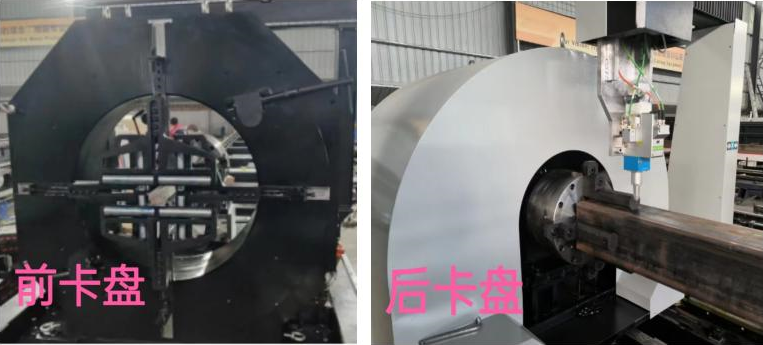
The left side is the front chuck, and the right side is the rear chuck.
This chuck is equipped with a diameter of 220 mm and has a self-centering function. The front chuck is manually operated and the rear chuck is pneumatic. The two sides are clamped to automatically find the center of the pipe.
When the purchased raw materials are not in accordance with national standards, there may be a certain deviation in size. Manual chucks can better fit the pipes and ensure their cutting accuracy.
6.2. Intermediate intelligent material support trailer
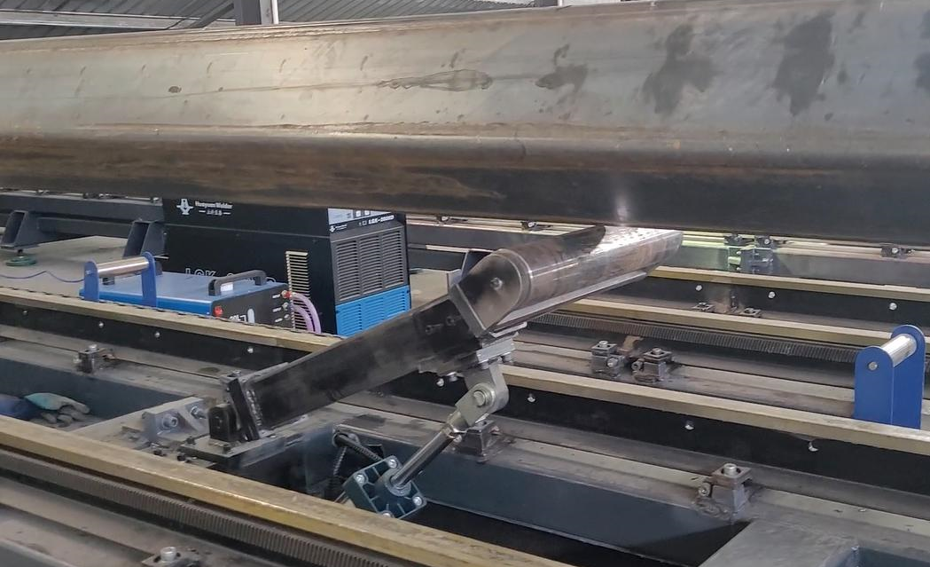
Firstly, it serves as the intermediate support. And secondly, when cutting 12 or 6 meters of material, if there is no support from the intelligent bracket in the middle, there is a risk of material sinking during the cutting process, which cannot guarantee cutting accuracy.
Installing the central intelligent trailer avoids this problem.
6.3. Lead Rail
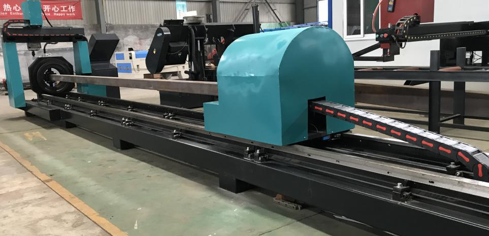
We use industrial heavy-duty guide rails (train type guide rails), which are not easily deformed when cutting large pipes for a long time.
6.4. Rack: VASTUN from Germany
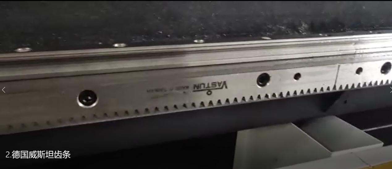
Adopting German imported VASTUN racks for higher cutting accuracy.
6.5. Fixture
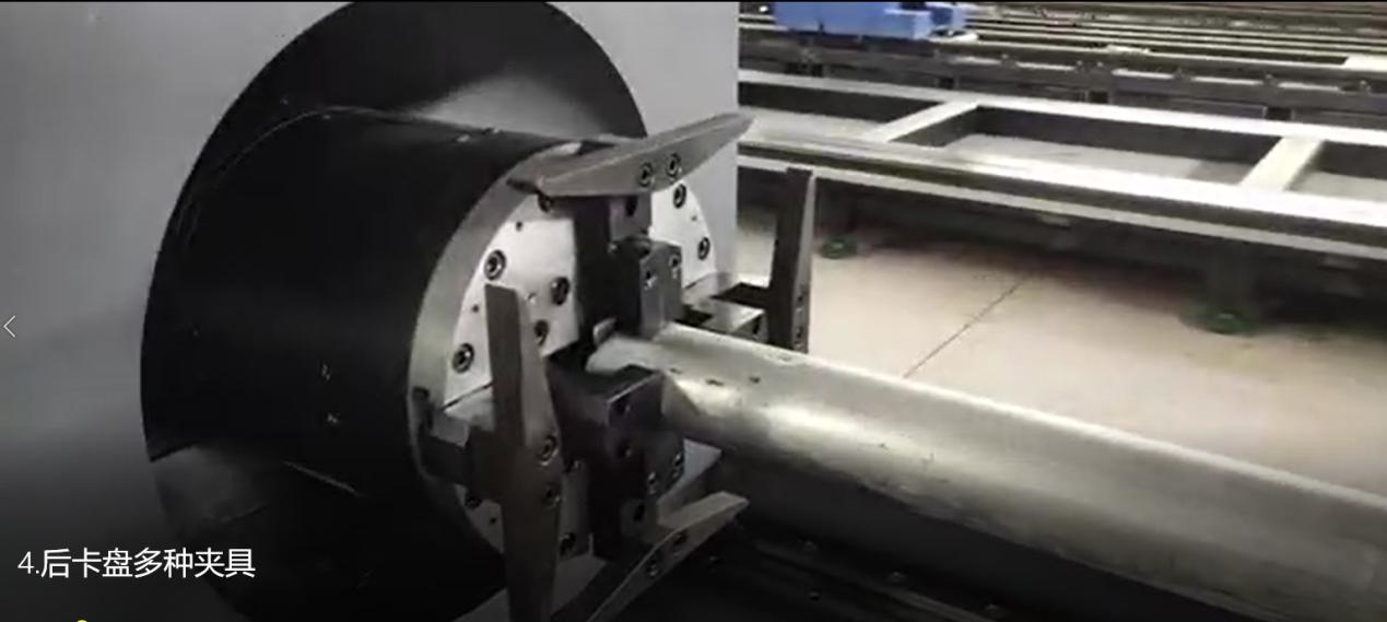
When cutting different types of profiles, different fixtures can be equipped according to the shape of the profile.
- Control system
7.1. Characteristics
– Hardware board replacement, stable and reliable, with simple wiring.
– Support manual box operation to improve production efficiency.
– You can use a file to set the speed, or use the system to set the speed.
– File speed setting supports linear speed and synthetic speed.
– The power clamp displays the maximum size of the machining graphics, which is intuitive and convenient.
– Graphics can be zoomed in and out.
– The limit switch can be used as a return to zero switch, which is simple and convenient.
– The starting positioning of processing is simple, without considering the swing axis.
– During processing, it can move forward or backward, and can be offset and returned.
– Parameter backup and parameter restoration.
– Optional hole start cutting, convenient and fast.
7.2. System performance parameters
Control accuracy: up to ± 0.001 mm;
Maximum operating speed: 25000 mm/min.
7.3. Electricity consumption
| Item | Power consumption (kW) | Total |
| Laser Source | 1.5 | 13 kW/h |
| Machine Lathe | 10 | |
| Water Chiller | 1.5 |
- Customer site requirements for machine tool installation (to be prepared by the customer before the equipment arrives)
| Series No. | Content |
| 1 | Installation site cement foundation ≥ 150 mm. |
| 2 | Power supply capacity: not less than 45 kVA. |
| 3 | Power supply requirements:
1) 380 V ± 5 % 50 Hz / 220 V ± 5 % 50 Hz; 2) The stability of three-phase voltage is less than ± 5 %; 3) Three wire power supply imbalance less than 2.5 %; 4) It is recommended to use a regulated power supply if it does not meet the above power supply requirements.
Note: The power supply voltage should not have sudden jumps or power outages, otherwise it may cause damage to the equipment, CNC system, and laser. A good grounding (with a grounding resistance of less than 10 Ohms) is required. |
| 4 | Compressed air supply requirements:
1) Gas supply pressure: 16 kg (1.6 MPa); 2) Dew point temperature not exceeding 5 degrees Celsius: oil content ≤ 0.003 ppm, fixed particles ≤ 0.01 micrometers. |
| 5 | Laser working gas and cutting auxiliary gas: air, oxygen, nitrogen. |
| 6 | Cutting pipes: smooth, flat, evenly rolled, with an elliptical deviation of no more than 3 mm in diameter, meeting ISO standards. |
| 7 | Installation site foundation requirements: seismic resistance level 6.
If there is a large earthquake source near the machine tool, it is recommended that the purchaser build an isolation trench when making the foundation. |
| 8 | Installation site and environmental requirements for CNC cutting machines:
1) Temperature requirement: – 10 ~ + 55℃ (the laser must be placed in an environment of + 18℃~25℃.); 2) Humidity requirement: < 80 % non-condensing. |
| 9 | Requirements for using coolant in chillers: The purchaser must comply with the cooling fluid requirements for chillers proposed by the supplier.
If the supplier does not use the cooling fluid, the cooling water pipe of the chiller may freeze, leading to further equipment damage, and the supplier is not responsible for warranty. |
| 10 | Equipment operators should have a high school or vocational school education level or above, and should have experience in operating computers and general CNC machine tools.
The equipment should be equipped with a programming computer. |
- Acceptance requirements:
– The foundation of the entire machine should meet the requirements of basic installation.
– There are no significant sources of impact around the machine.
– All welding seams of the machine must not have welding defects such as cracks, pores, slag inclusions, etc.
– All moving parts of the machine must not be loose or stuck.
– All connectors and components inside the electrical box must not be loose.
– Check whether all safety protection devices are sensitive and reliable in operation.
– Check that all gas supply lines must not have any leakage (soap liquid inspection method).
– Machine grounding must be good.
- Equipment delivery information
– Provide a technical document (including programming manual).
– Provide a set of operation manuals.
– Provide a set of safety operating procedures.
10.1. Training
Training method: online or on-site installation training.
10.2. Technical services
– After the equipment is inspected and accepted by the purchaser, the supplier promises to provide a 24-month warranty for the equipment, excluding human damage and providing lifelong repair services;
– The supplier provides discounted spare parts and services to the demand side during the warranty period;
– The accuracy of the laser will be maintained for approximately 3-5 years.
When the purchaser uses the machine for 3-5 years, the purchaser will notify the supplier to provide on-site service.
The supplier promises to send technical personnel to provide laser calibration services to maintain stability, and the purchaser will reimburse travel expenses.
- Customers Show
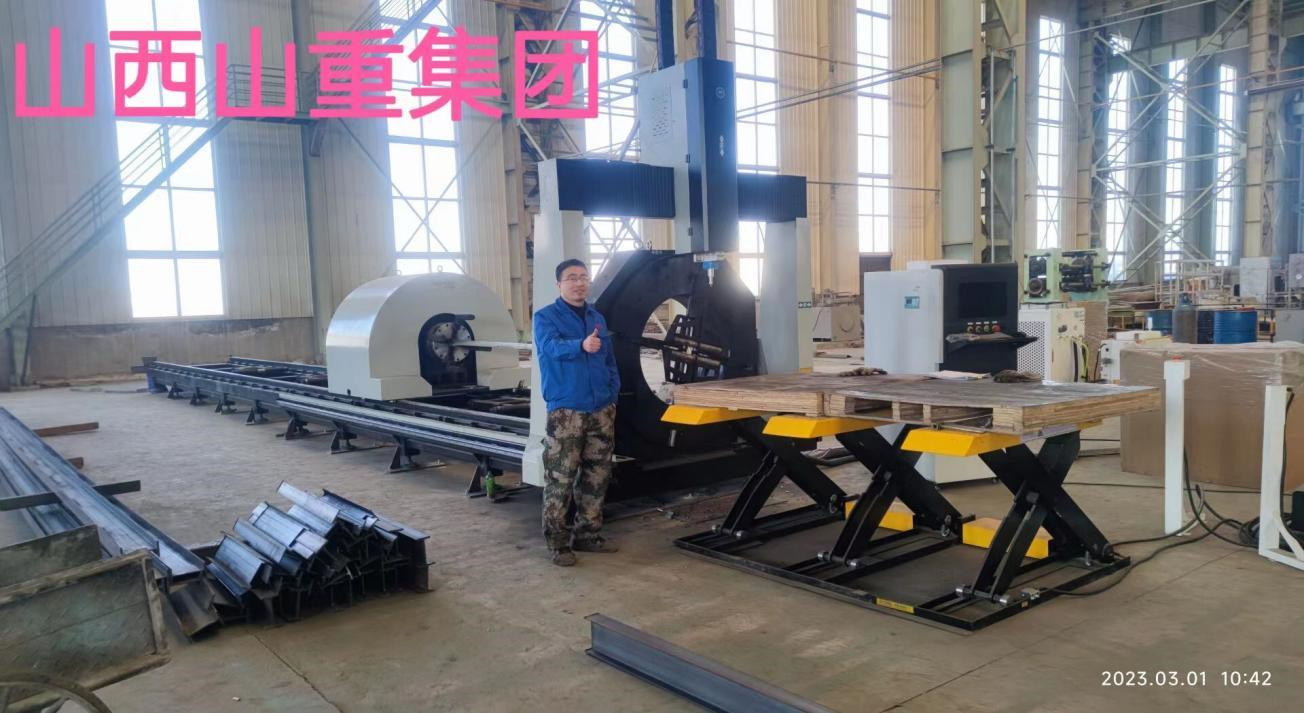
SHANXI Heavy Industry Group
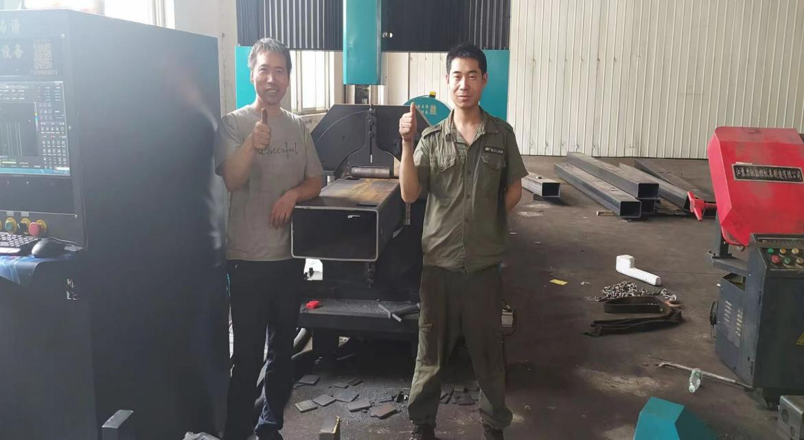
SINOTRUCK GROUP
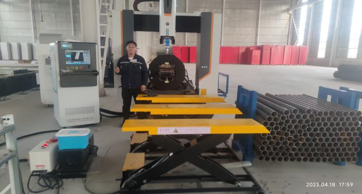
CHINA STATE CONSTRUCTION
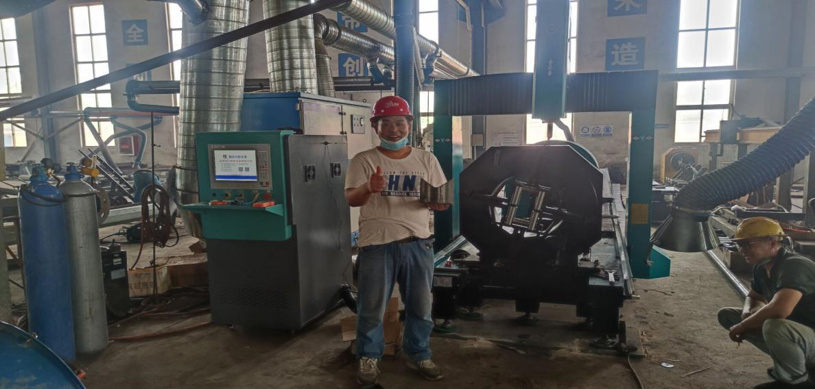
XCMG GROUP
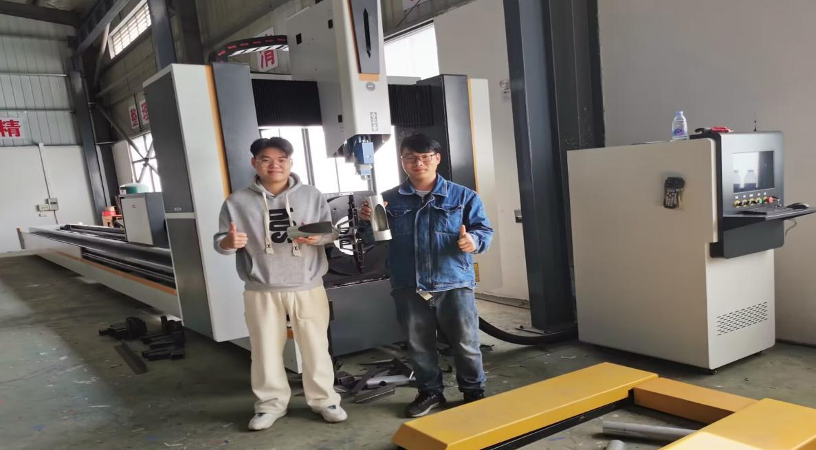
VOLKSWAGEN GROUP
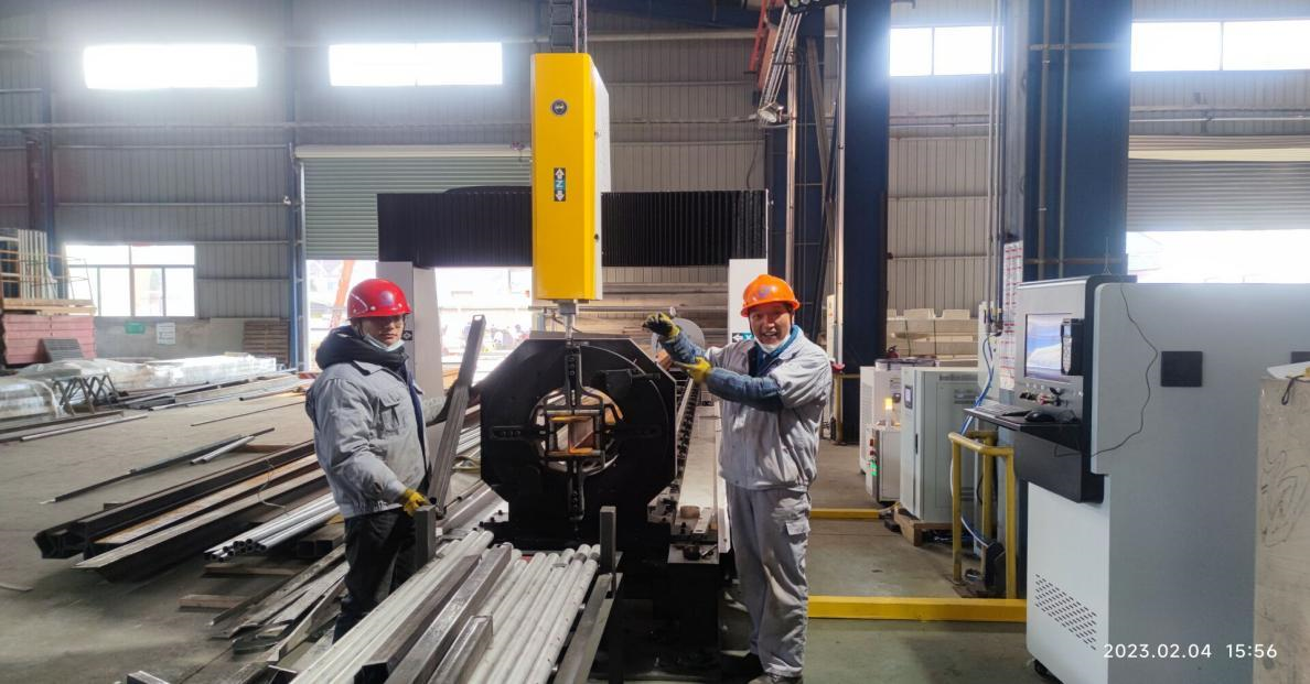
FAW GROUP
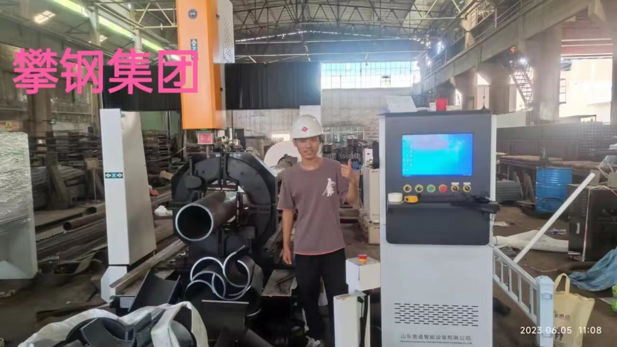
PANGANG (ANSTEEL) GROUP Company Limited.
- Renowned customers
